Motivation
Do you ever worry about your pets while you're away from home? Concerned that the temperature might be too hot or too cold, or that a fire could break out, and you wouldn't know until it's too late?
For this project, I wanted to create a modular environmental monitoring system that alerts pet owners when critical conditions surpass predefined thresholds. This system would send real-time notifications to the user and allow continuous monitoring of the home environment.
I envision a temperature and smoke detection module that can be mounted on the wall, featuring a screen to display real-time temperature readings. Multiple modules could be placed throughout the home, all transmitting data to a central microcontroller-based hub. The main microcontroller would act as an interface, allowing users to check sensor readings at any time.
All sensor data would be stored in an online database, enabling historical tracking and analysis. To notify users of dangerous conditions, the system would send text messages or mobile notifications, ensuring that pet owners stay informed about their pet's safety, no matter where they are.

Minimal Viable Product (MVP)
For my MVP, I will focus on:
- Understanding and integrating the necessary sensors for monitoring desired environmental conditions.
- Developing the Arduino code to process sensor data and display it on a TFT screen and an OLED screen.
- Designing and fabricating housing for both the main microcontroller and TFT screen using CAD modeling and 3D printing.
Materials:
- ESP32 DevKit
- BMP280 Pressure and Temperature Sensor
- MQ2 Gas Sensor
- TFT 2.4" 240x320 Screen
- 0.96" OLED Screen
- Breadboard
- Lots of wires
- 3D Print PLA
Calibration of Temperature Sensor
For this project, I am using a BMP280 Pressure and Temperature Sensor, which communicates via the I2C protocol.
Wiring was straightforward, except for identifying the correct I2C address for the sensor.
By default, the sensor operates at address 0x76, but when running an I2C scanner, the device was not detected.
To resolve this, the SDD pin needed to be pulled high to change the address to 0x77.
After updating the code to reflect this new address, the sensor was successfully detected and functioned as expected.
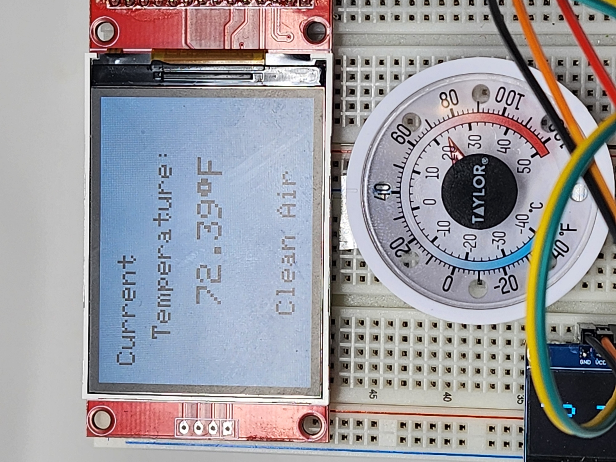
Calibrating this sensor was relatively simple. After allowing it to run for a period of time to reach equilibrium,
I compared its temperature readings to a reliable thermometer. I found that the sensor's readings had an error of 2.6°F,
which I compensated for in the software by applying an offset.
Calibration of Gas Sensor
The next step was to calibrate the gas sensor. The MQ2 gas sensor requires three connections: VCC, GND, and an analog output.
According to the sensor's documentation, it needs to run for at least 24 hours upon first use to fully warm up before calibration.
After this initial burn-in period, it typically requires 5-10 minutes to warm up and stabilize its readings during normal use.
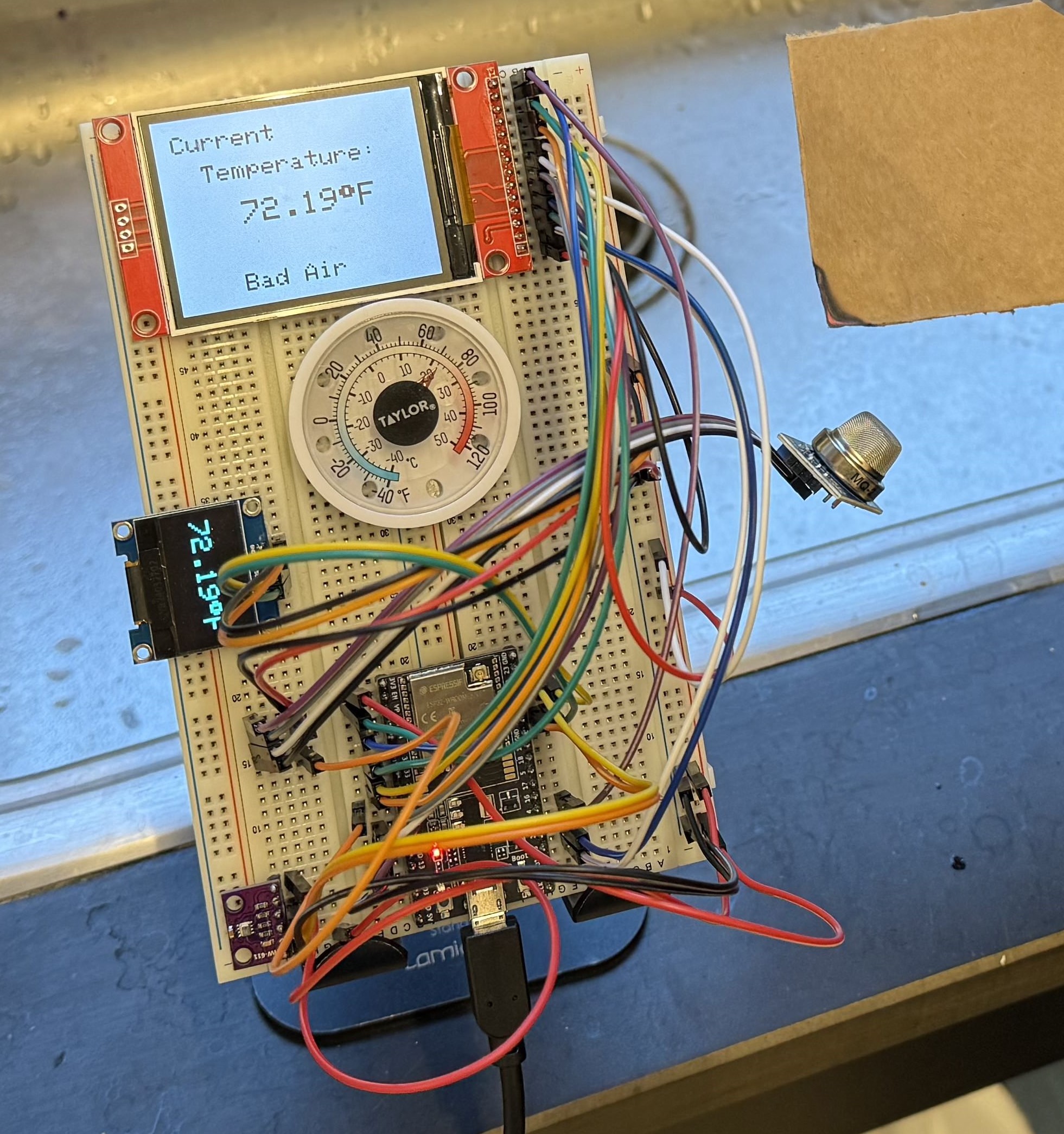
The MQ2 sensor is capable of detecting various combustible gases, including propane, methane, smoke, and carbon monoxide. For this project, smoke detection was the primary focus. To calibrate the sensor, I conducted an experimental test setup, exposing the sensor to clean air and smoke multiple times to record its response.
During the calibration process, I introduced smoke by burning a small piece of cardboard near the sensor while logging real-time data. The sensor readings showed a clear spike when exposed to smoke, followed by a gradual return to baseline in clean air. After analyzing multiple test runs, I determined that a sensor reading of 1900 is a reliable threshold to distinguish between normal and smoke-filled air conditions.
MATLAB Code
% Define serial port and baud rate
port = 'COM11';
baudRate = 9600;

% Open serial connection
arduinoObj = serialport(port, baudRate);

i = 1;
while true
    try
        % Read line from serial
        data(:,i) = readline(arduinoObj);
        sensorValue = str2double(data);
        fprintf('Sensor Value: %d\n', sensorValue(i));
        % Wait 1 seconds before next reading
        pause(1);
        i = i+1;
    catch
        % Stop if there's an error
        disp("Error. Check connection.");
        break;
    end
end

% Close serial connection
clear arduinoObj;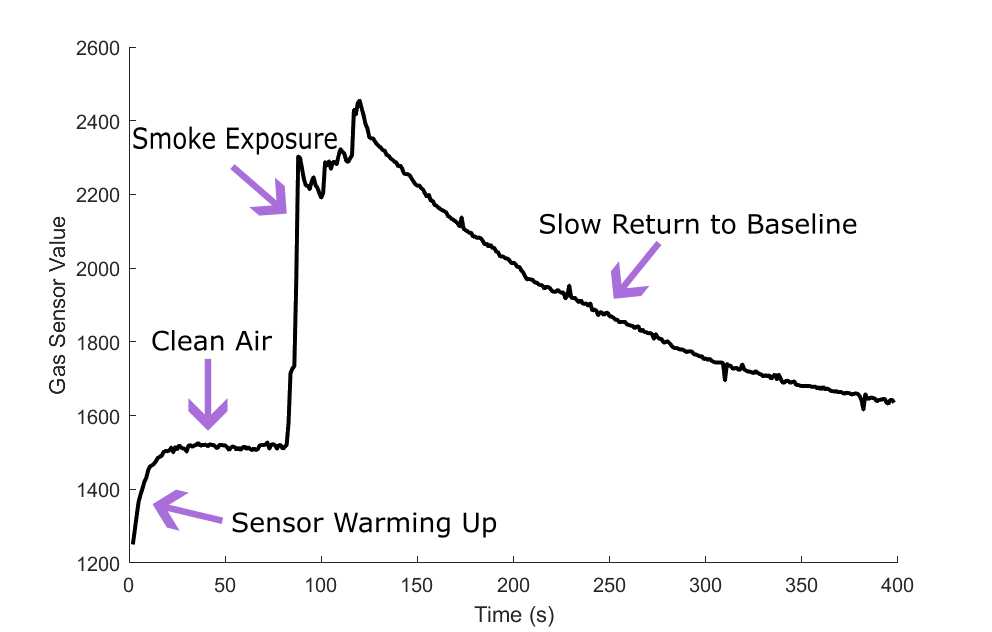
Coding it All with Screens
TFT Pinout
| TFT Screen | ESP32 | TFT Screen | ESP32 |
|---|---|---|---|
| T_IRQ | GPIO 36 | T_OUT | GPIO 39 |
| T_DIN | GPIO 32 | T_CS | GPIO 33 |
| T_CLK | GPIO 25 | SDO (MISO) | GPIO 12 |
| LED | 3.3V | SCK | GPIO 14 |
| SDI (MOSI) | GPIO 13 | D/C | GPIO 2 |
| RESET | EN / RESET | CS | GPIO 15 |
| GND | GND | VCC | 3.3V |
OLED Pinout
| OLED Screen | ESP32 |
|---|---|
| GND | GND |
| VCC | 3.3V |
| SCL | GPIO 22 |
| SDA | GPIO 21 |
BMP280 Pinout
| BMP280 Sensor | ESP32 |
|---|---|
| VCC | 3.3V |
| GND | GND |
| SCL | GPIO 22 |
| SDA | GPIO 21 |
| SDD | 3.3V |
MQ2 Gas Sensor Pinout
| MQ2 Sensor | ESP32 |
|---|---|
| VCC | 3.3V |
| GND | GND |
| A0 | GPIO 26 |
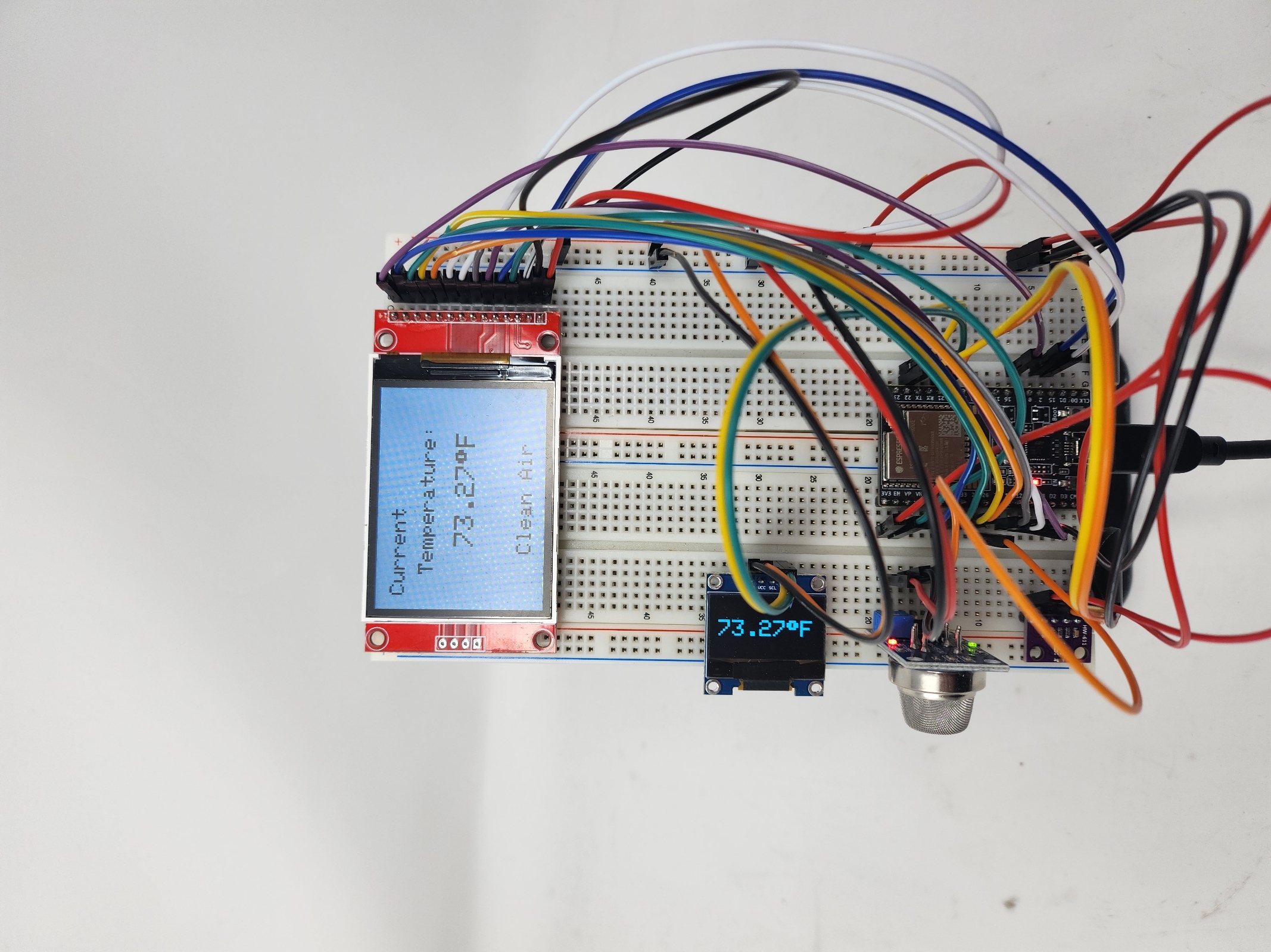
Using the Arduino IDE along with the SPI, Wire, Adafruit_GFX, Adafruit_SSD1306, Adafruit_BMP280, and TFT_eSPI libraries, I implemented object-oriented programming to structure the code efficiently. This allowed me to program the temperature and gas sensors to collect real-time data and display the readings on both the TFT and OLED screens.
Arduino Code
#include <SPI.h>
#include <Wire.h>
#include <Adafruit_GFX.h>
#include <Adafruit_SSD1306.h>
#include <Adafruit_BMP280.h>
#include "TFT_eSPI.h"

#define SCREEN_WIDTH 128
#define SCREEN_HEIGHT 64
#define OLED_RESET     -1
#define SCREEN_ADDRESS 0x3C

class GasSensor{
    int pin;
    int threshold;
    unsigned long previousUpdate;
    int interval;
    float gasSensorVal;
    bool newValAvailable = false;

    public:
    GasSensor(int sensorPin, int updateInterval){
        pin = sensorPin;
        pinMode(pin, INPUT);
        threshold = 1900; //above this is bad air
        interval = updateInterval;
        previousUpdate = 0;
    }

    void Update(){
        if((millis() - previousUpdate) > interval){
        previousUpdate = millis();
        gasSensorVal = analogRead(pin);
        newValAvailable = true;
        }
    }

    bool newData(){
        return newValAvailable;
    }

    float getGasVal(){
        newValAvailable = false;
        return gasSensorVal;
    }
};

class TempSensor{
    Adafruit_BMP280 bmp;
    int error;
    float tempSensorVal;
    unsigned long previousUpdate;
    int interval;
    bool newValAvailable = false;

    public:
    TempSensor(int updateInterval, int readingError){
        interval = updateInterval;
        error = readingError;
    }

    void init(){
        Wire.begin();
        bmp.begin(0x77);
    }

    void Update(){
        if((millis() - previousUpdate) > interval){
        previousUpdate = millis();
        tempSensorVal = bmp.readTemperature() * (9.0/5.0) + 32.0 - error;
        newValAvailable = true;
        }
    }

    bool newData(){
        return newValAvailable;
    }

    float getTempVal(){
        newValAvailable = false;
        return tempSensorVal;
    }
};

class TFTScreen{
    TFT_eSPI tft;
    public:
    TFTScreen(){}

    void init(){
        tft.begin();
        tft.setRotation(1);
        tft.fillScreen(TFT_BLACK);
        staticText();
    }

    void staticText(){
        tft.setCursor(20, 20);
        tft.setTextSize(3);
        tft.println("Current");
        tft.setCursor(50, 60);
        tft.println("Temperature:");
    }

    void updateScreen(float gasSensorVal, float tempSensorVal) {
    tft.fillRect(80, 240/2 - 20, 200, 50, TFT_BLACK);
    tft.fillRect(80, 190, 200, 50, TFT_BLACK);

    tft.setCursor(90, 240/2 - 10);
    tft.setTextColor(TFT_WHITE);
    tft.setTextSize(4);
    tft.print(tempSensorVal, 2);
    tft.print((char)247);
    tft.println("F");

    tft.setCursor(80, 200);
    tft.setTextColor(TFT_WHITE);
    tft.setTextSize(3);
    if (gasSensorVal >= 1900) {
        tft.println("Bad Air");
    } else {
        tft.println("Clean Air");
    }
    }
};

class OLEDScreen{
    Adafruit_SSD1306 display;

    public:
    OLEDScreen() : display(SCREEN_WIDTH, SCREEN_HEIGHT, &Wire, OLED_RESET) { }

    void init(){
        Wire.begin();
        display.begin(SSD1306_SWITCHCAPVCC, SCREEN_ADDRESS);
        display.clearDisplay();
    }

    void updateScreen(float tempSensorVal){
        display.clearDisplay();

        display.setTextSize(3);
        display.setTextColor(SSD1306_WHITE);
        display.setCursor(0, 20);
        display.print(tempSensorVal);
        display.print((char)247);
        display.println("F");

        display.display();
    }
};

GasSensor MQSensor(26, 5000);
TempSensor BMPSensor(5000, 2.6);
TFTScreen tftScreen;
OLEDScreen oledScreen;

void setup(){
    Serial.begin(115200);
    tftScreen.init();
    BMPSensor.init();
    oledScreen.init();
}

void loop(){
    MQSensor.Update();
    BMPSensor.Update();
    if (MQSensor.newData() || BMPSensor.newData()) {
    tftScreen.updateScreen(MQSensor.getGasVal(), BMPSensor.getTempVal());
    oledScreen.updateScreen(BMPSensor.getTempVal());
    }
}
CAD Modeling of Device Casing
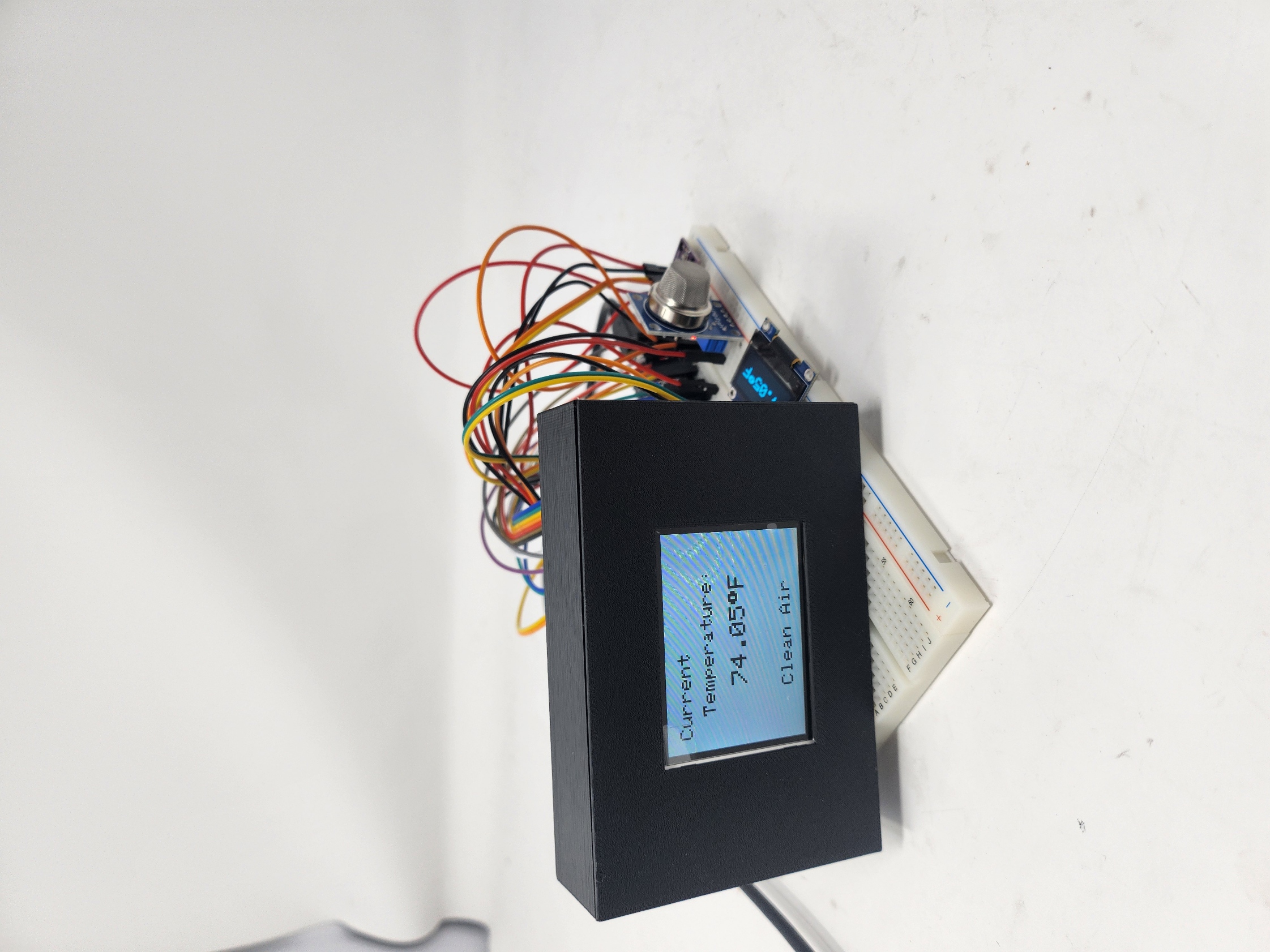
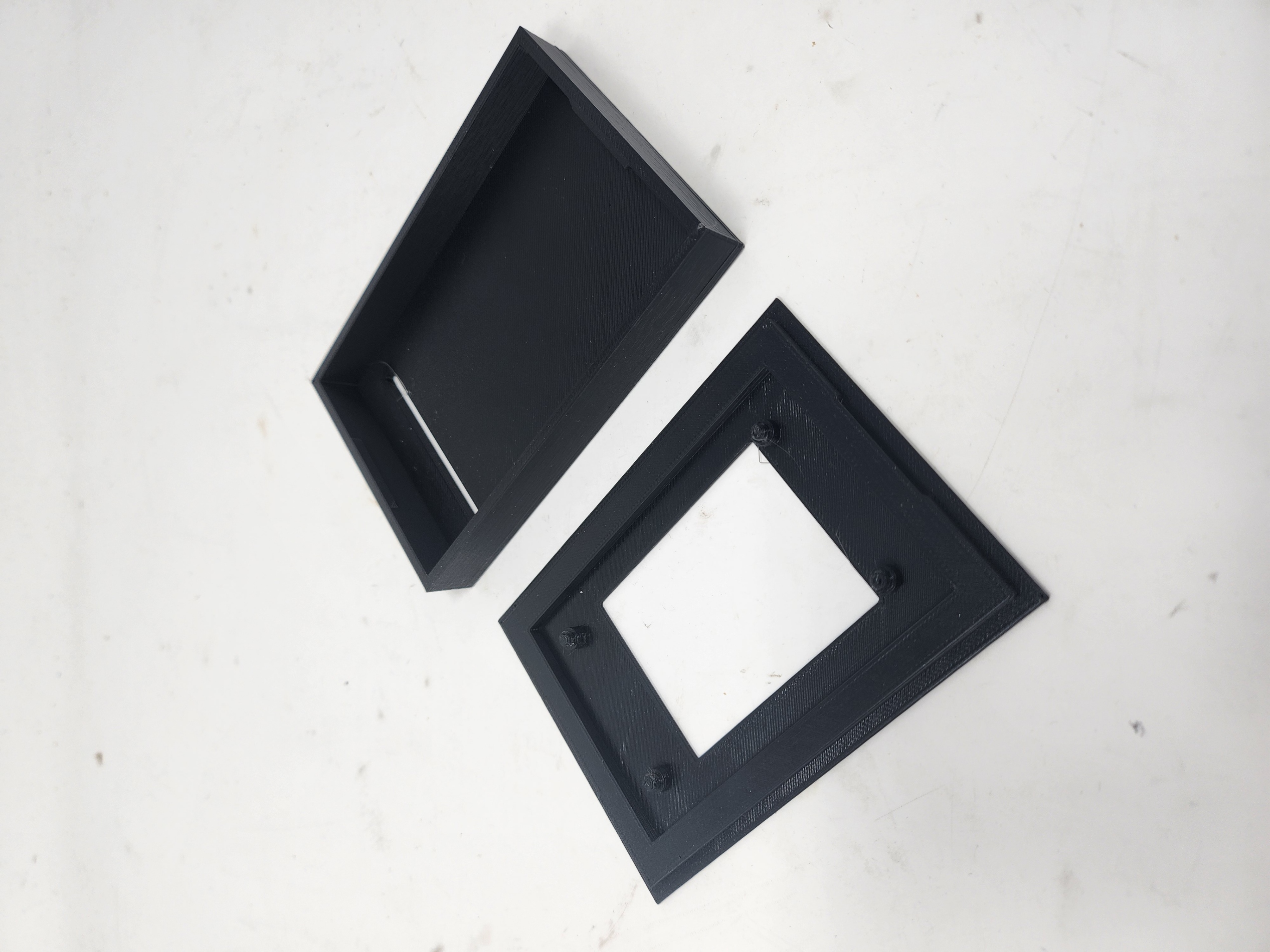
The casing for the TFT screen needed to accommodate both the display and the ESP32 microcontroller. Below and to the right is my initial design concept for this enclosure. I aimed to create a snap-fit box where the TFT screen securely clicks into place. Through multiple test prints and measurements, I determined that a 3.3mm diameter circular snap feature with a 0.75mm fillet allowed the screen to fit snugly while remaining easy to install and remove.
The next step is to refine the design to ensure proper interfacing between the TFT screen, ESP32 microcontroller, and the necessary wiring connections. This will involve optimizing the internal layout to neatly accommodate all components.
In the future, I plan to modify the casing to resemble a cat's face, integrating 3D printing techniques to achieve a multi-color print using a single extruder. The casing for the OLED screen will follow a similar design but will also incorporate dedicated space for the sensor modules.
Future Steps
Moving forward, the next major step is to separate the sensor modules and OLED screens from the main ESP32 microcontroller and establish a wireless communication system using Wi-Fi. The goal is to transmit real-time sensor data to a Firebase database, enabling remote monitoring and alerts. This will involve setting up initial internet connectivity and ensuring reliable data transmission between multiple ESP32-based sensor nodes and the central controller.
Another focus will be designing casings for the OLED screen and sensor modules using the ESP32 Xiao. Using the Xiao will allow the module to be small and light weight for easy wall mounting. Additionally, I plan to refine the design of all the enclosures to resemble a cat's face and experiment with 3D printing techniques to achieve multi-color printing with a single extruder.
Power consumption will be an important aspect to think abuot. Since the sensor modules and OLED displays may need to operate wirelessly for extended periods, I will look into implementing low-power modes of the ESP32, where the sensor modules will wake ever so often and send data up to the Firebase before returning to sleep, and selecting an appropriate rechargeable battery to ensure long-term operation.
Finally, setting up the initial internet connection for seamless device pairing and data synchronization will be challenging. This may include implementing a setup mode where users can configure Wi-Fi credentials via an HTML web interface hosted by the ESP32. Aesthetics of the TFT screen and this HTML web serve will be the last thing I focus on.