Week 3: Hand Tools and Fabrication
This week we did a full tour of the lab to learn about all the tools and materials we can use and how to safely use them. We learned how to drill a hole and tap it; got a look at how to solder and desolder, and got to see how to use a drill press and scroll saw. Slowly finding on my own where certain materials are and what vast selection of material the lab has. The main assignment of this week was to create a kinetic sculpture composed of pieces cut from at least two different materials. We need to include at least one static joint, at least one prismatic or revolute joint.
For this week's assignment, it was a lot of improvising because I didn't really know what I wanted my end product to be. So to start off I did prototyping with cardboard. A lot of cardboard. I learned how to make gears in Fusion360. There is a nice Add-In option that lets you make spur gears with ease instead of having to draw out the gear by "hand." It took some time playing around with the numbers to finally realize that to get a certain pitch diameter, you just have to optimize the values of "Number of Teeth" and "Module." The pitch diameter is basically these two values multiplied by each other. Other than that, by watching some YouTube tutorials on gear making in Fusion360, I set the value "Backlash" = 0.125mm, "Root Fillet Radius" = 1.588mm, "Pressure Angle" = 20 degrees, and "Gear thickness" (just for prototyping) = 3.68mm (thickness of the cardboard). Backlash to my understanding is the clearance of each gear tooth to another gear tooth. Root Fillet Radius to my understanding is the fillet of the base of the tooth of the gear. It lies within the main circle of the gear (without the teeth). The pressure angle is the angle between the direction that the teeth exert force on each other.
So overall independent gear parameters:
Backlash = 0.125mm
Root Fillet Radius = 1.588mm
Pressure Angle = 20 degrees
Gear Thickness = 3.68mm
After learning how to make gears in Fusion360, I decided to make some sort of gear-clock thing. So I lasercut the gears and then screwed them onto a circular base. After going all the way with this, having cut my gear out of acrylic and the circular base out of wood, and learning that metal wires exist, I decided to make my gear-clock thing into something more sculpture-y. So I made 3 tiny abstract dancers out of metal wire by hand and it honestly turned out better aesthetically than I planned. So the overall process for this project was (1) learning how to make gears in Fusion360, (2) making a prototype CAD model, (3) lasercut that model with cardboard, (4) optimize it and fix mistakes, (5) final lasercut with wood and acrylic.
Prototyping
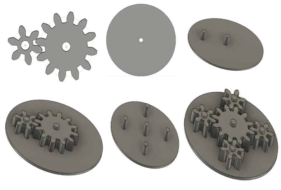
First I started off with 2 gears simply in a 2:1 ratio. I got used to making gears and changing the pitch diameter to my liking. The next step was making the baseboard, placing the gears on that board, and then making axles that they can sit on to turn on the board where the gear holes were. After getting the small gear's position in relation to the parent gear correct, I added 3 more small gears around the parent gear and added their respective axles to the base.
So overall parameters:
Parent Gear Number of Teeth = 12
Small Gear Number of Teeth = 6
Module = 2.5
Gear hole diameter = 5mm (for an M5 screw)
Baseboard diameter = 74.84mm
After lasercutting it out of cardboard, I realized that I vastly undershot the pitch diameter of the gears and my gears were way too small. It seemed that I had the measurements wrong in my head and was converting centimeters to millimeters correctly.
2nd try at Protoyping
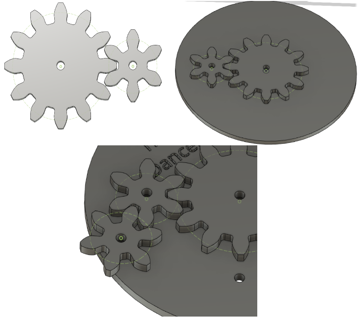
This time I made everything bigger. I increased the gear module to be 5. With this increase in size I made the baseboard have a diameter of 150mm. This protype is the size I had in mind. After getting the 4 gears I wanted into place, this gear clock is rather boring because it doesn't really do much other than you turn the parent gear and it turns 4 other small gears. So to make it more interesting, I added more small gears. I put them in such a way that the small gear that is connected to the parent gear would turn another small gear. Before I went to lasercut it, I started to wonder how to animate in Fusion360 to see what my gears would look like when they turned. So by watching a couple Youtube videos I learned how to As-Built Joints and how to motion link them. The one thing you have to change is that since the parent gear is twice as big and has twice as many teeth than the small gear, you have to multiply the angle of the motion link by 2. And with the gear that is one the parent gear, the direction has to be reversed to get the gears in sync as if one is pushing the other. After playing around the animation of the gears moving I lasercut the baseboard, the parent gear, and 4 out of the 8 small gears to try out my idea.
2nd try parameters:
Parent Gear Number of Teeth = 12
Small Gear Number of Teeth = 6
Module = 5
Gear hole diameter = 5mm (for an M5 screw)
Baseboard diameter = 150mm
Can animate the gears!
3rd try Prototyping
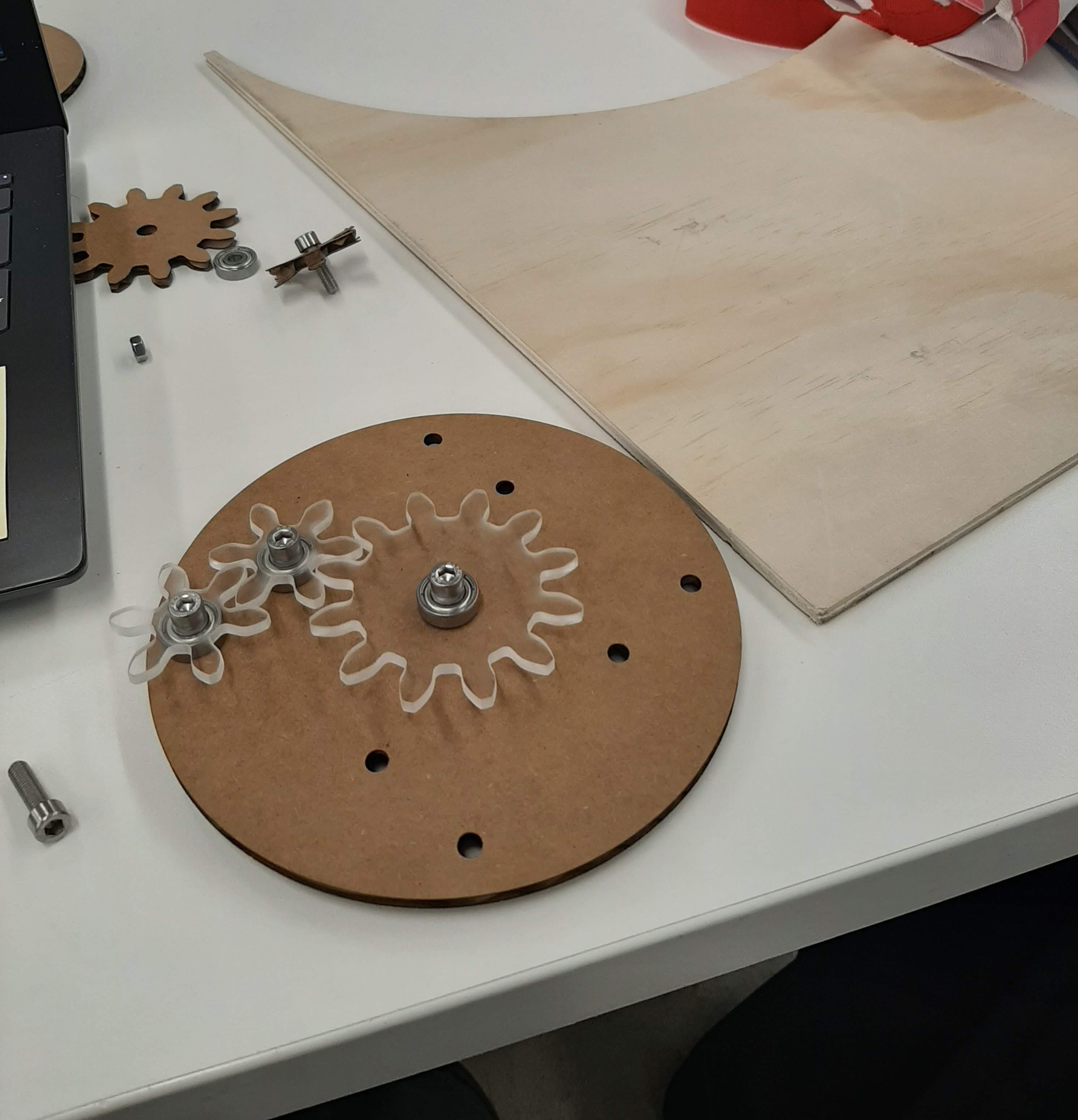
After putting those pieces together, I realized it was quite hard to turn the gears with the parent gear in the middle. So to make the process of turning the set of gears, I decided to have another gear that was the same size as the parent gear connected to the system. This way you don't have to awkwardly reach for the parent gear when the rest of the small gears are put in place. After this, I laser cut the gears out of acrylic so that the system of gears would move more smoothly. With the cardboard, one gear would catch the middle of another and just start bending the cardboard piece. So with the acrylic, the system worked better and the aesthetics of my project were on the incline.
Since the piece of acrylic I was lasercutting didn't 100% match the thickness of the parameters in the power-speed manual for the lasercutter, I chose values that were close to the respective parameters and had to do a bit of experimenting. It took 3 tries to get it right. When cutting acrylic, I learned that speed is very important and that it has to go much slower to get through the piece of acrylic all the way. I also believe that it can't be too much power and too fast or the piece will melt itself back into the material you were trying to cut it out of.
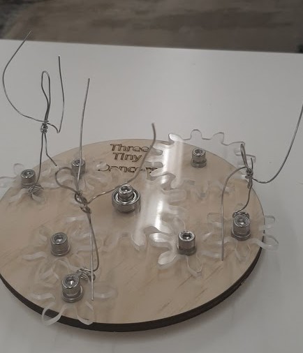
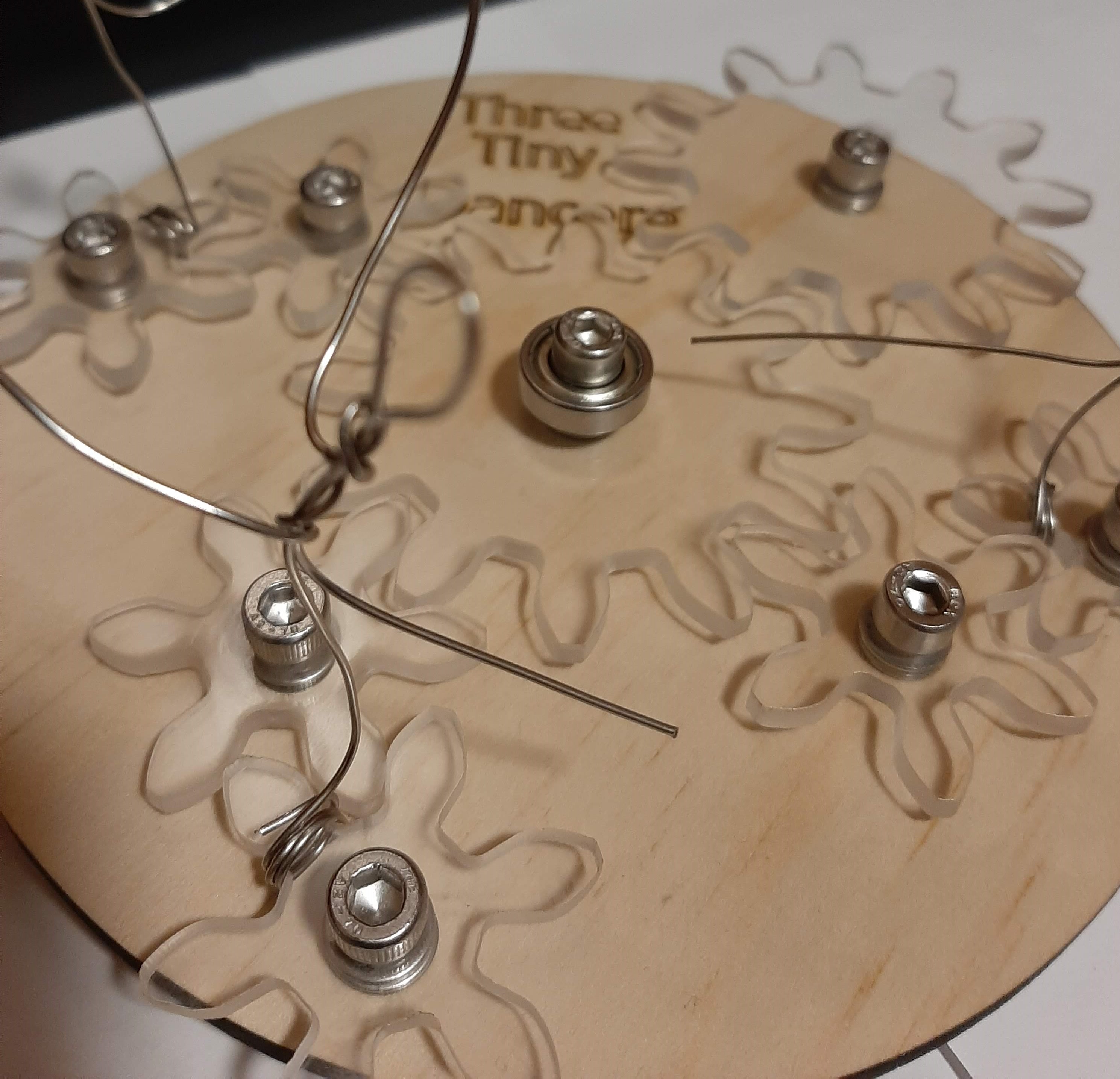
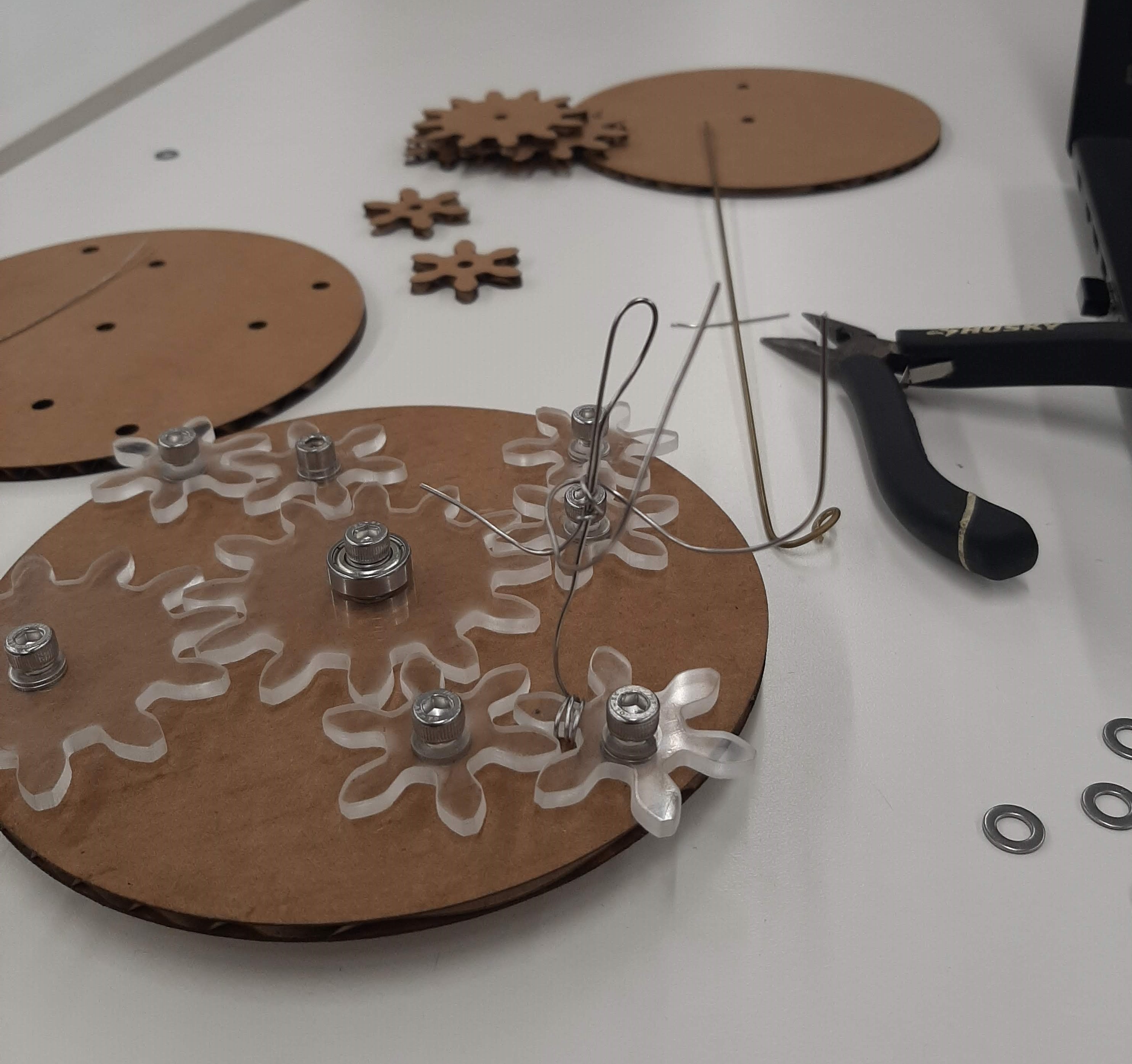
When screwing in my gears, I am using an M5 x 20 screw, an M5 washer, and a rotary bearing (just for the parent gear). (Contrary to what is seen in the photo of multiple rotary bearings, I later realized that you do not need that many. The rest of them just need spacers to turn.)
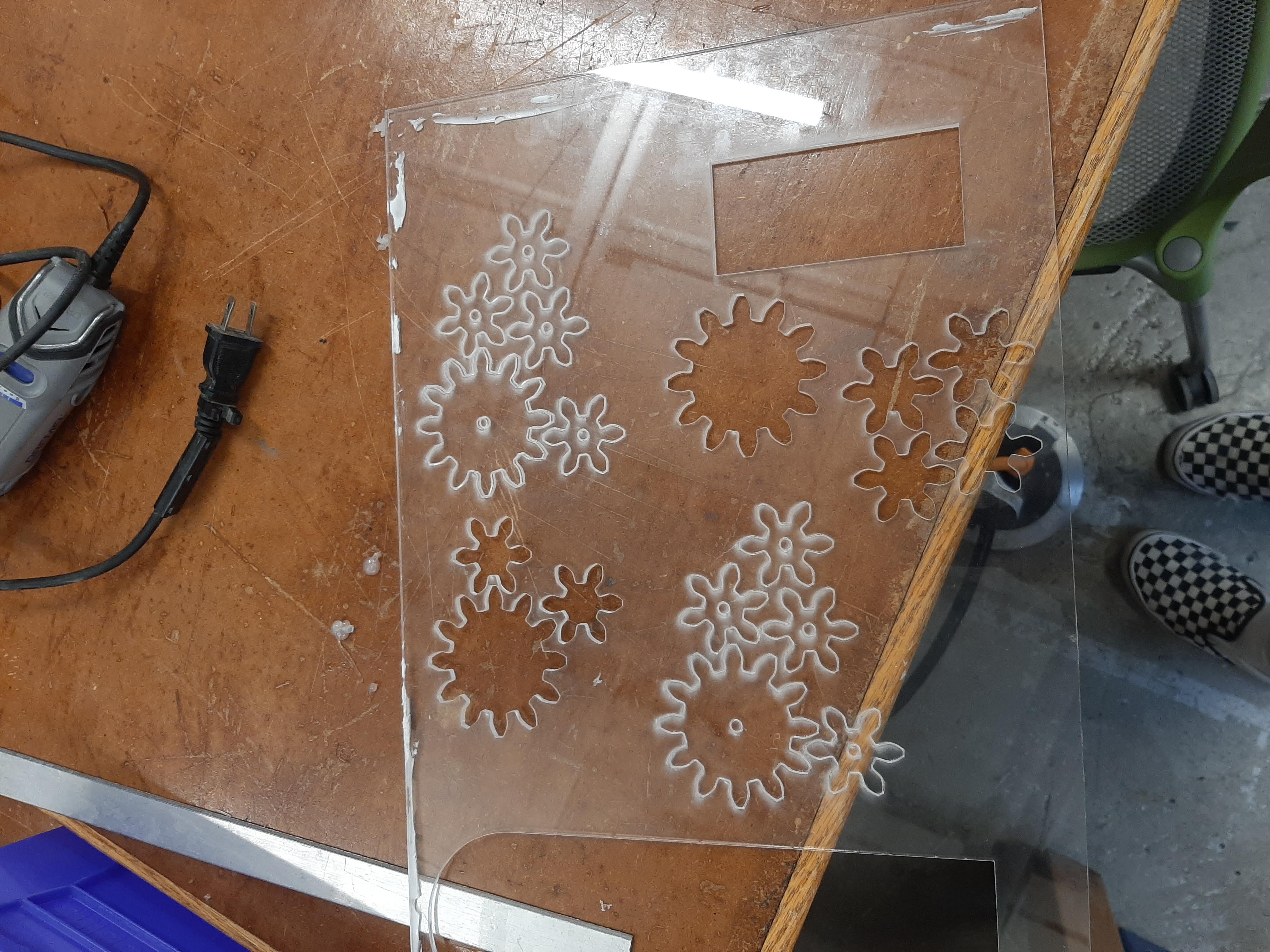
Fail attempts at lasercutting acrylic
Look at the lasercut go~
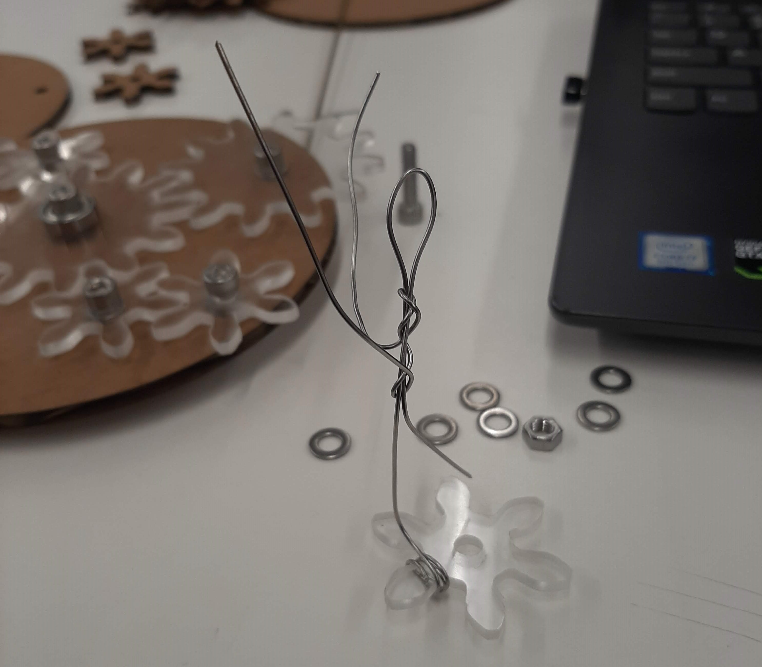
Are we Human, or are we Dancer?
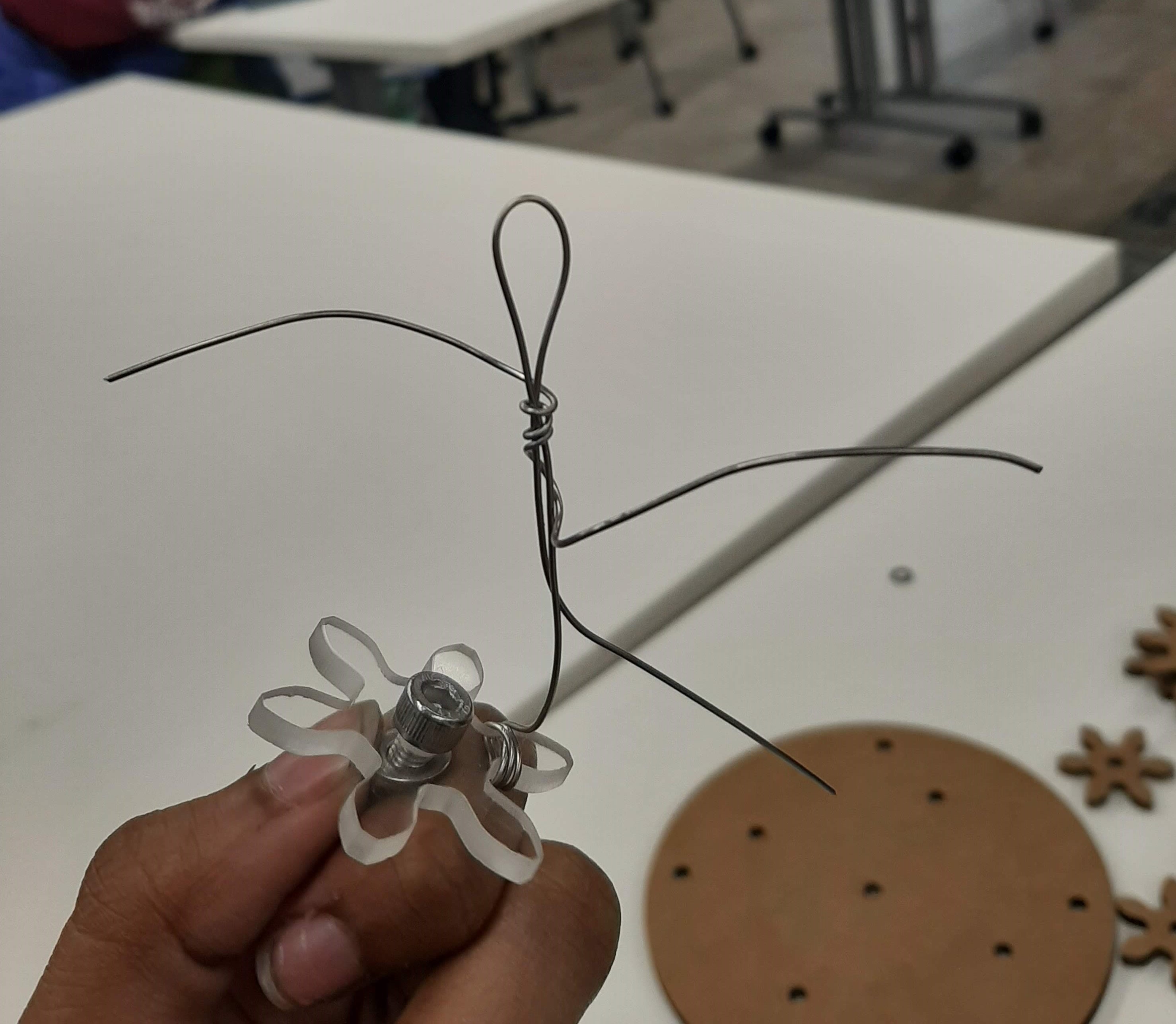
With all the acrylic gears on the cardboard baseboard, my original idea was starting to come together. But then I started to think my design looked a little bare. So I went looking around the material cabinets in the lab and found metal wire. At, first I had the idea of wrapping them around the small gears and having the wires make abstract shapes when you turn the gear system. But after doing some bending of the wire with a pair of pliers, I got the idea to make them into little, abstract people and make them look like they were dancing. This would add more to the sculpture part of the assignment.
Final Cut
Because of the three dancers I added, I also decided that I wanted to engrave "Three Tiny Dancers" on my final cut of the baseboard. With that, I was done prototyping and was ready to make a final cut of my baseboard with wood. I lasercut the base with wood and then transferred over the acrylic gears with the dancers on them. With the lasercutting, since the wood is pretty thick, I had to turn down the speed (the 30 that is used for cardboard), turn up the power (from the 60 that is used for cardboard) and do the cut over like 3 times to ensure that it cut through all of the way. I am very happy with the way it looks! Very aesthetically pleasing. The one thing that I would work on going forward is figuring out why some of the screws become undone when I turn the gear system.