Week 2: 2D Design and Cutting
This week learned about using computer aided design (Fusion 360), lazer cutting, and vinyl cutting. I have used SolidWorks before, so it was very interesting to see how Fusion 360 was different, and I have to say it is a lot easier to use Fusion 360. It has a more friendly userface and was pretty easy to pick up and learn compared to SolidWorks. The main assignment of this week was to use the lazer cutting to make press fit pieces of cardboard. And with the right things put into consideration, like kerf, you can build something that doesn't require any supplementary material like glue. The basic layout of lazercutting something is making a 2D sketch in Fusion360, extrude it into 3D, make a 2D projection of that extrusion, convert that to a DXF file, and then feed that file to the lazer cutter. Using a lazer cutter seems scary and convoluted at first. But after a couple of cuts, the process just came down to a number game of getting the slots of the piece correct.
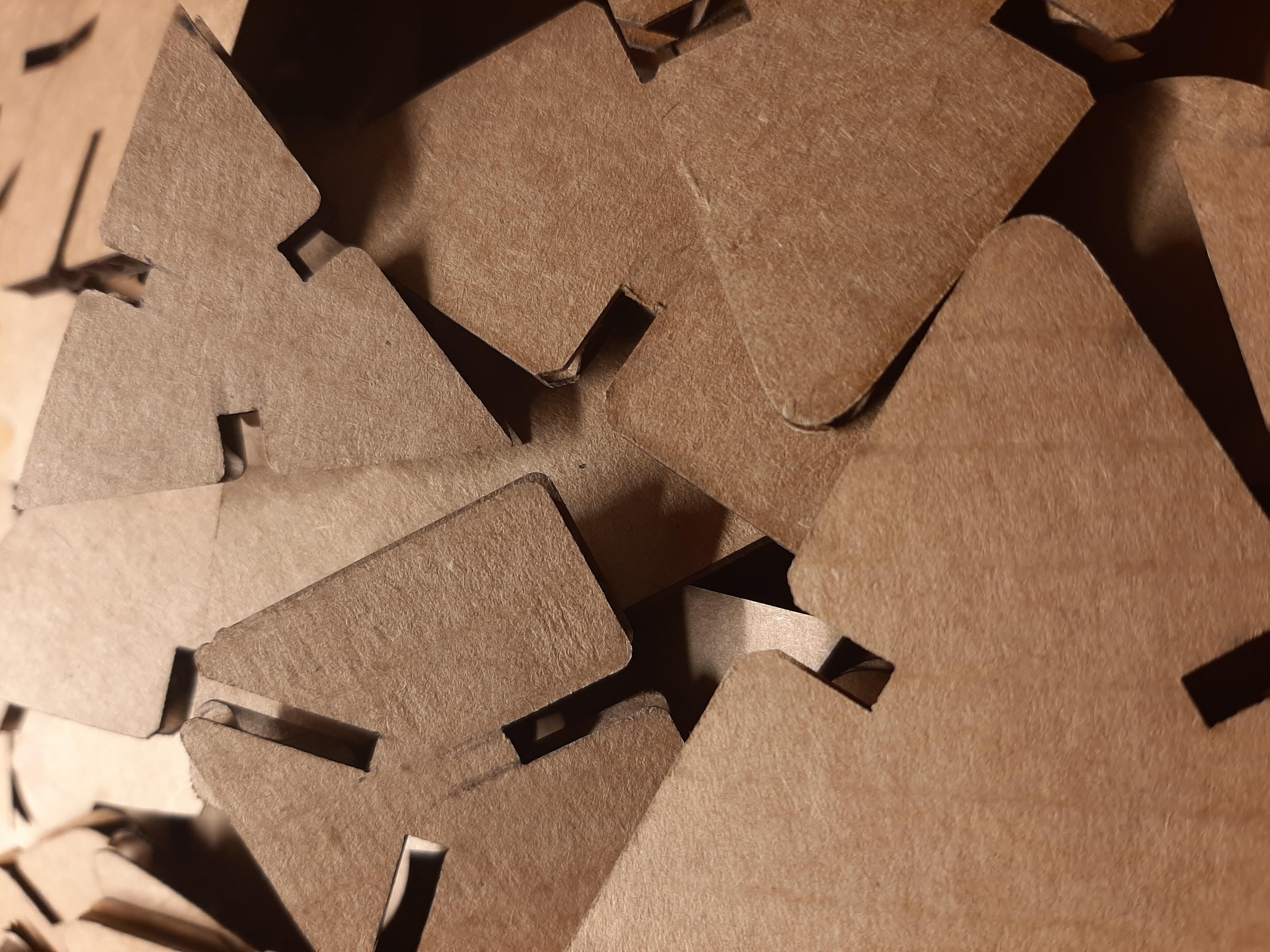
For this week's assignment of a press fit kit, I didn't really have an overall end shape in mind. I decided to experiment with the slots on a square piece and also tried out a simple triangle piece. For the square piece, instead of having four slots on each of the four respective sides, I decided (with inspiration from the internet) to try to put some slots in the corners of the square. For the triangle piece I just wanted to try making a press fit piece on my own following the instructions from the lecture. I like the number three, and a triangle has three sides and can build some cool things.
When building the pieces, the most important thing to remember is the kerf of the laser, which is a constant, and our case was 0.2mm. Next, for the width of my notches, they are (thickness-kerf). The thickness is the thickness of the material and kerf is accounting for how much material is going to be burned away. When making the notches, if you don't account for kerf, your notches will be too big and won't get that nice strudy grip on another piece. My first CAD model had a thickness of 4.4mm, but when I cut it didn't really fit. Knowing I took into account kerf, I used a digital calliber to measure the cardboard I was going to lasercut, and I found that the was actually around 3.8mm. Changing this made the rest of my pieces work perfectly. A little to perfectly actually, as they are very far to put together, and even harder to take apart. Maybe next time I should round up a tiny bit more.
When using the lasercutter I used these parameters:
max_speed = 60
min_speed = 60
power = 30
First Cut
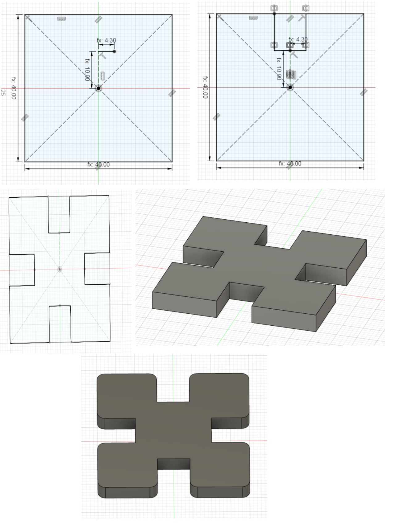
First I started off with a simple square piece and a simple triangle. For the square piece, first I made a 2D sketch of a square with a side length of 40mm, thickness of 4.4mm, and a kerf of 0.2mm. After drawing the square you want to make a construction line from the center of the square upwards of length (side/4). This will serve as the top of the notch. Then to the get the width of the notch, you make a line from the top of the notch out toward the side of length, (thickness-kerf)/2. Very important to take kerf into play.Then you make a line from the endpoint of the line just made, to the respective side of the square. After that, to get the the full slot, you just have to mirror the two lines that were made. Now that the full slot is done, we can circular mirror/pattern it around the square so we don't have to draw it 3 more times. Now that the full sketch is done, we can extrude it out a distance of the amount, thickness. After this we can add some fillets to make the piece have more curved edges. In this first cut the fillet radius is around 2mm. It is important to note that one can only add fillets after they have extruded their sketch. So now that we want to print this sketch, including the fillets we have now added to the 3D model, we have to project the 3D model back down onto the 2D plan so that we can tell the laser cutter to cut the 2D sketch. So after projecting it back down to the 2D plan, we can convert that sketch file into DXF and print on the laser cutter. This square piece I didn't end up cutting because when I looked at it on the print screen of the laser cutter, the notches seemed too wide, and they were in fact too wide because I had the wrong thickness as a variable. So if I would've cut them out, they wouldn't have fit nicely together as wanted.
So overall parameters:
side_length = 40mm
thickness = 4.40mm
kerf = 0.2mm
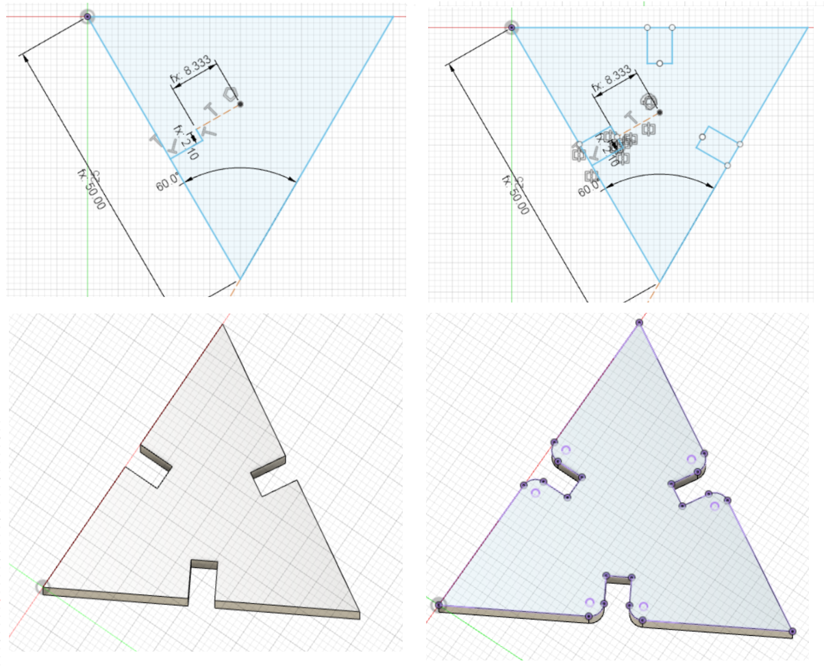
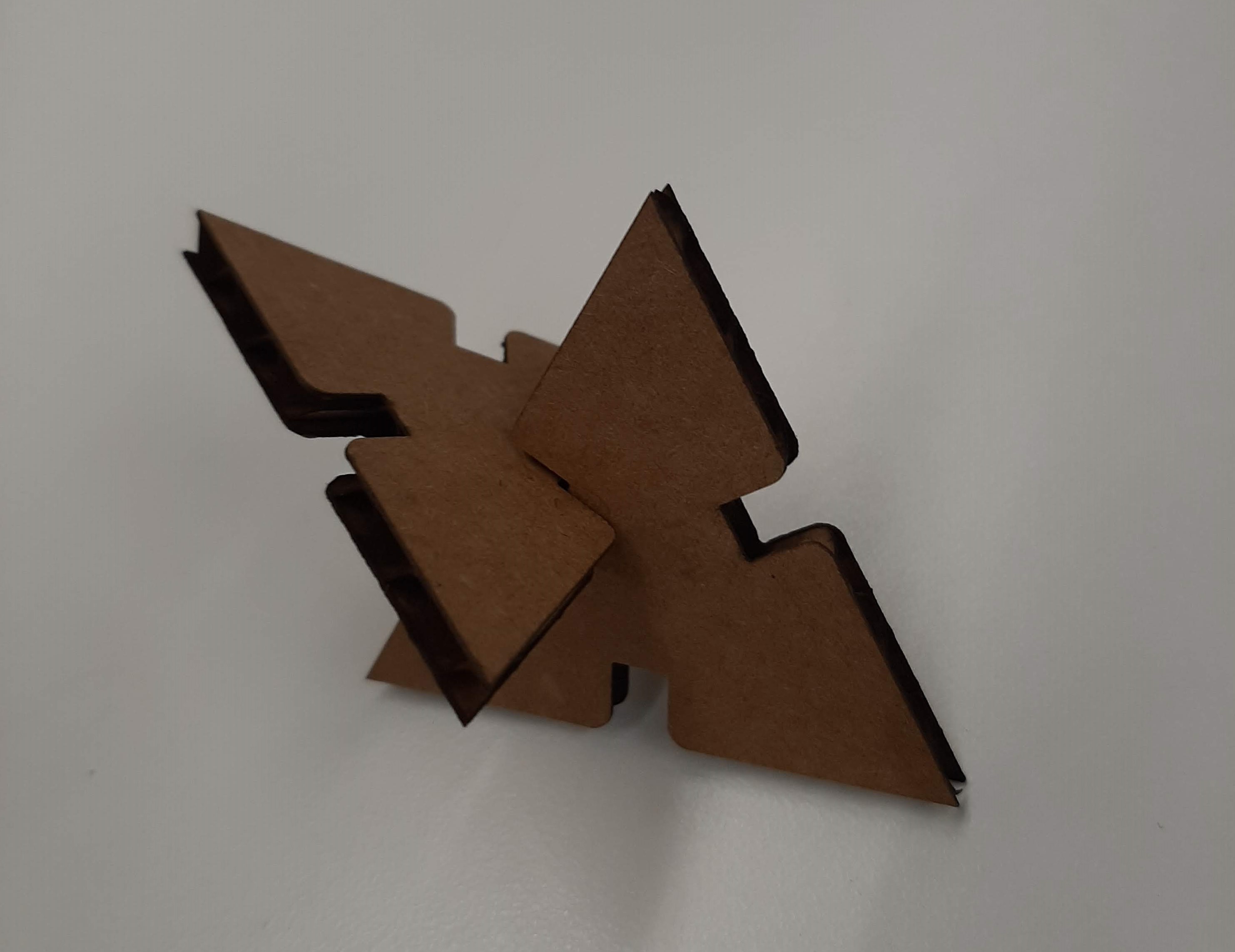
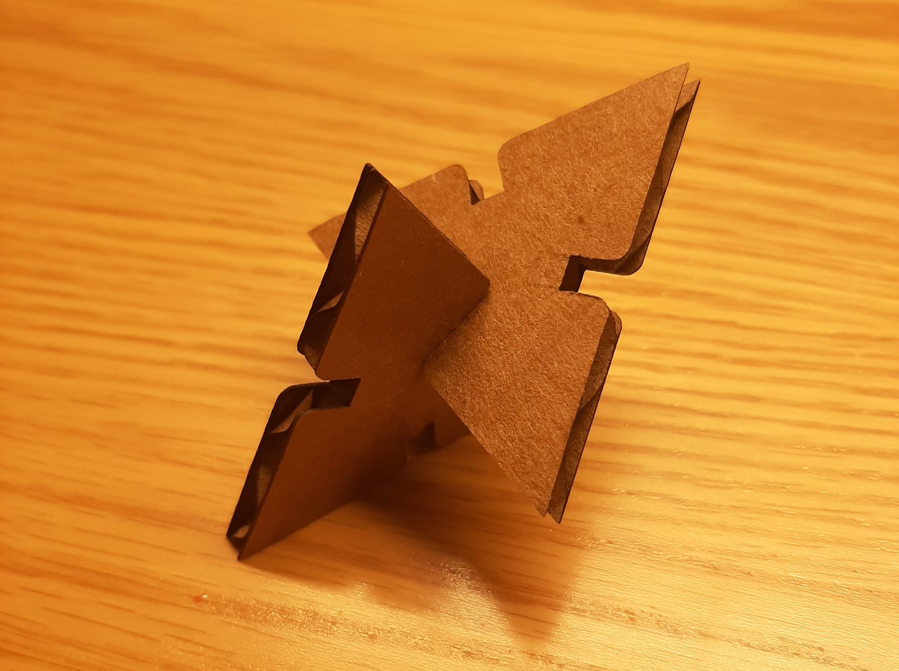
This triangle piece has the same process as the square piece. Instead this time the side length was 50mm. Thickness and kerf stayed the same at 4.4mm, and a kerf of 0.2mm. After drawing the triangle, I applied the same method of drawing the notch. This time the top of the notch was at (side/6) away from the center of the triangle. The width of the notch stayed the same at (thickness-kerf)/2. After the whole notch was drawn, I used circular pattern to get notches on the other two sides. After the sketch was done, I extruded it a distance of thickness. After this I made some fillets in the notches to help with the process of putting the pieces together. The fillet radius is around 2mm. This triangle piece I did laser cut, and after putting the pieces together, they didn't really hold onto each other. This is when I realized that their thickness was wrong. Using a digital calliber, I measured the thickness to actually be aroudn 3.8mm. After fixing this in my sketch, the triangle pieces fit perfectly together!
So final parameters:
side_length = 50mm
thickness = 3.80mm
kerf = 0.2mm
Notches are too big
Notches perfect!
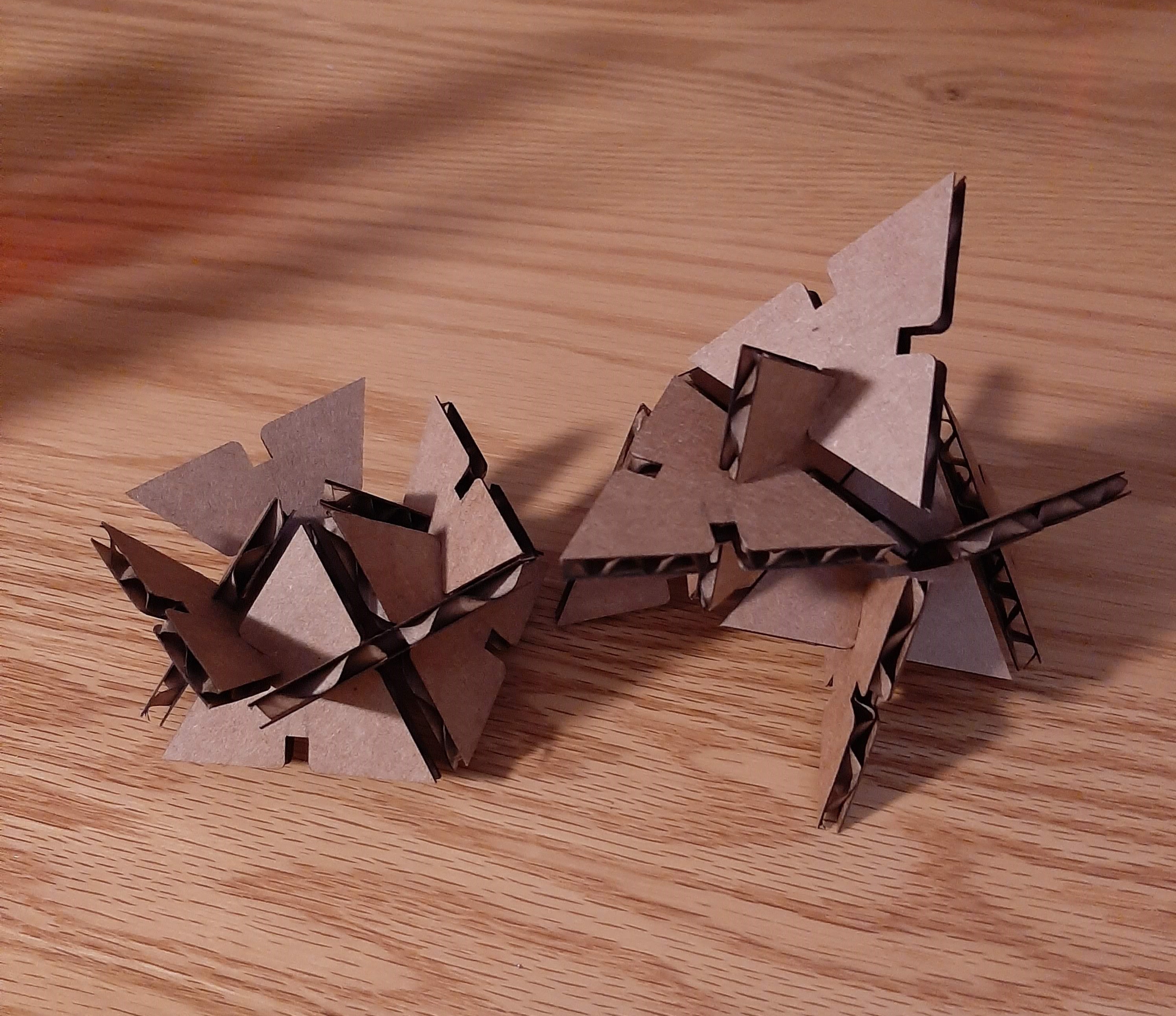
Can make abstract shapes!